\MMogPad
Disclaimer: I am new to doing write-ups of projects, so please let me know if there is any information you would like to know that I have not included here!
This project started as a response to seeing the HorixFFXIV game-pad collaboration. It seemed like an interesting concept but there were a few things I didn’t like.
- The ‘ergonomic’ design: I’m sure that for many people this design is really nice for their hands. For me though- the design feels terrible, and if I’m honest I don’t need so many buttons.
- Price: I am NOT paying $140 for an oversized macro-pad with joystick.
- Aesthetic: it is very ‘gamer’-y and to be honest I don’t find that to be very appealing. It is also HUGE. I don’t want most of my limited desk space to be taken up by some giant macropad.
- Its not pink.
So the first thing I needed was a macro-pad. For this i got a dumbpad by Keedb. Originally I had gotten six kits to make some for myself and friends as holiday gifts.
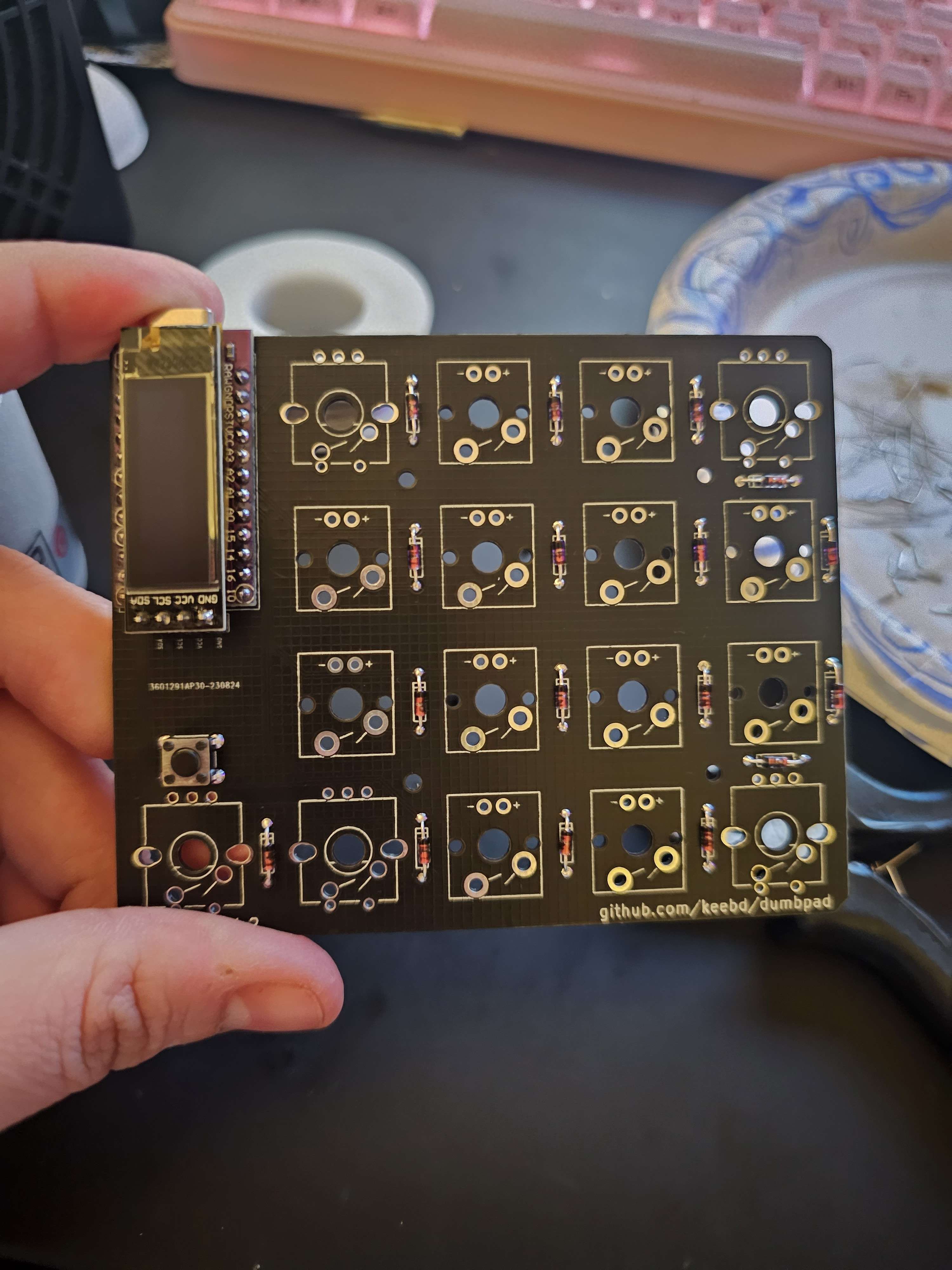 This was by far the easiest part of the project. Instructions for the macro-pad are simple enough to find online. You simply solder the arduino pro micro to the board, then you solder the screen to the board. In order to keep components isolated I added Kapton tape to the back of the OLED. While i doubt it would realistically cause a short- I’d rather be safe than sorry.
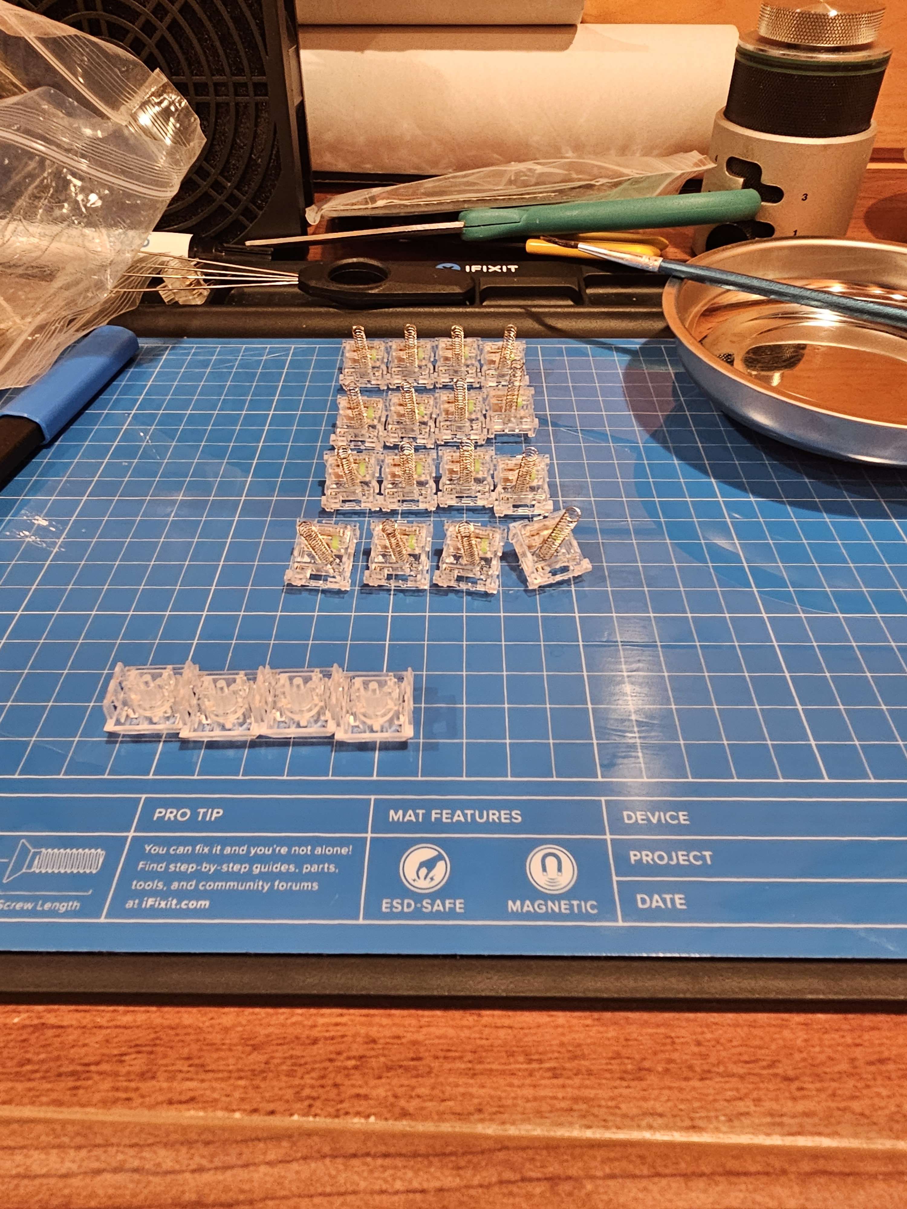
The next thing to do was just to flash the firmware. I was able to customise the macropad for each person. (I had to lube every switch for each person. Never again)
Once I decided to add a joystick to one I had to figure out WHERE. I took the time to look at the schematic and try to figure out which pins were available.
The schematic pointed to the encoders:
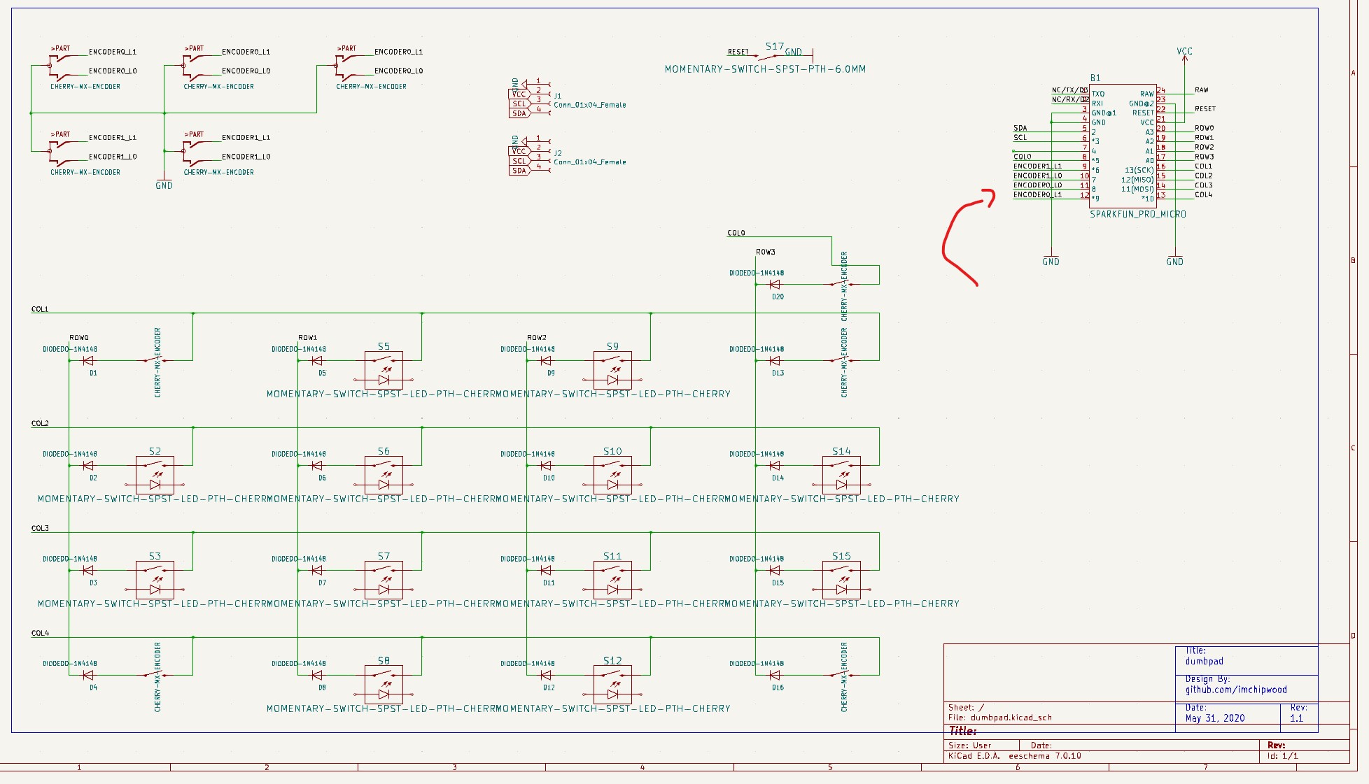
The joystick pins are as follows :gnd, x, y , 5v
I connected the 5v and gnd, and then connected X and Y to the encoder pins.

I had used QMK to flash the firmware onto the macropads. The change to add a joystick was deceptively simple:
I added the joystick enable to rules.mk
JOYSTICK_ENABLE = yes
Then I created a config.h file and the joystick info:
// Min 0, max 32
#define JOYSTICK_BUTTON_COUNT 0
// Min 0, max 6: X, Y, Z, Rx, Ry, Rz
#define JOYSTICK_AXIS_COUNT 2
Then I added the configuraiton for the joystick:
joystick_config_t joystick_axes[JOYSTICK_AXIS_COUNT] = {
` JOYSTICK_AXIS_IN(B4, 150, 400, 800),//y
JOYSTICK_AXIS_IN(B5, 750, 520, 150), //x
};`
The three numbers after the pins are the resistance values. The joystick I used was (originally) a psp joystick, later changed to a 3ds XL one.
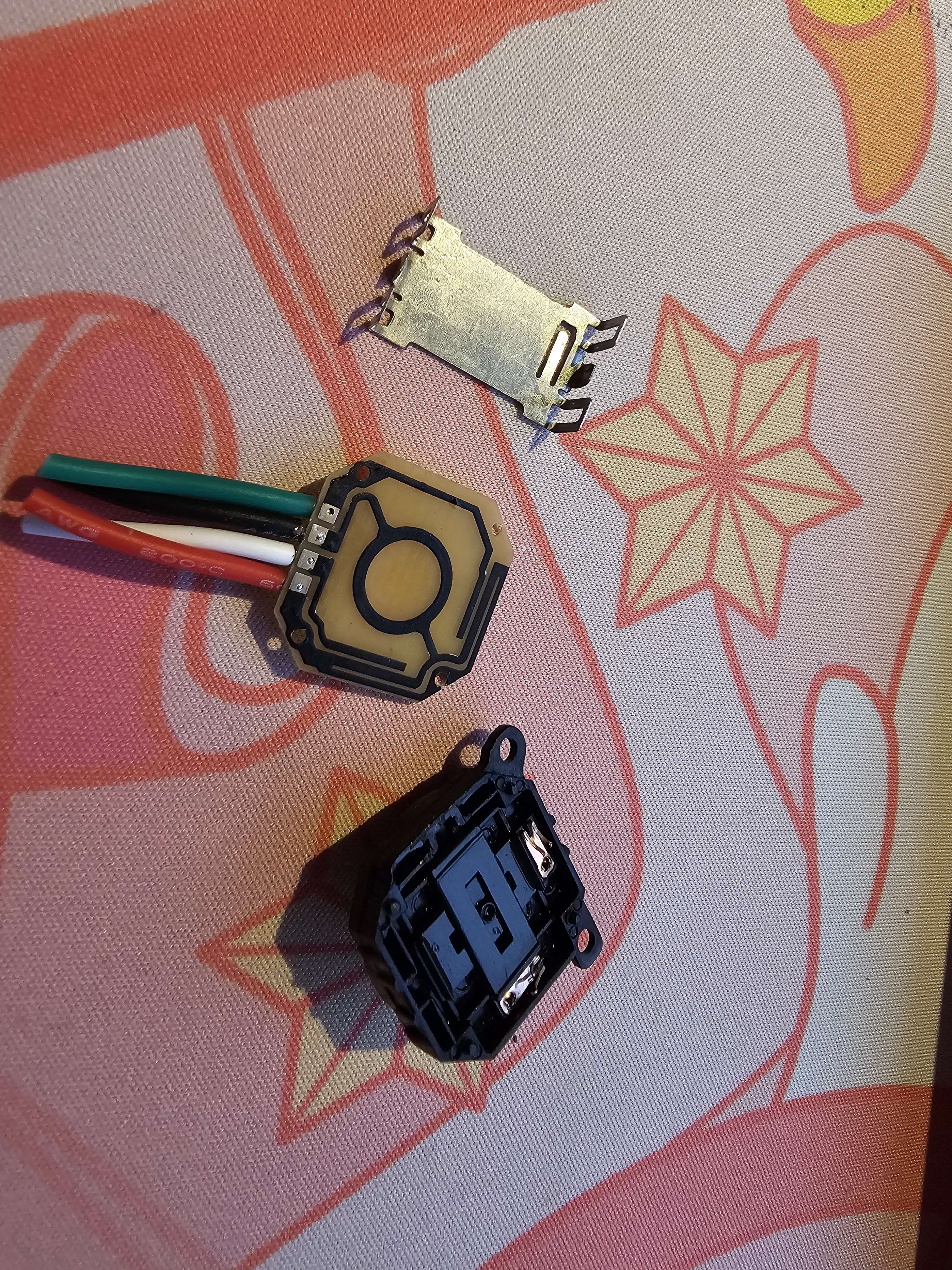
The copper pins in the joystick drag accross the traces on the PCB and they vary the resistance coming out of the x,y pins. To figure out the resistance values I needed to be able to measure the resistance going into the analog pins. To do this I used the ability serial print the input resistance values. This can provide an average Max, average Min, and the average resistance at rest.
Swapping the Max and Min can help change the orientation of the joystick, swapping up and down, and left and right.
Once all of this was settled and written onto the firmware I could begin testing and design a case.
I am NOT good at case design. In fact- I suck. But by golly did I do my Best. 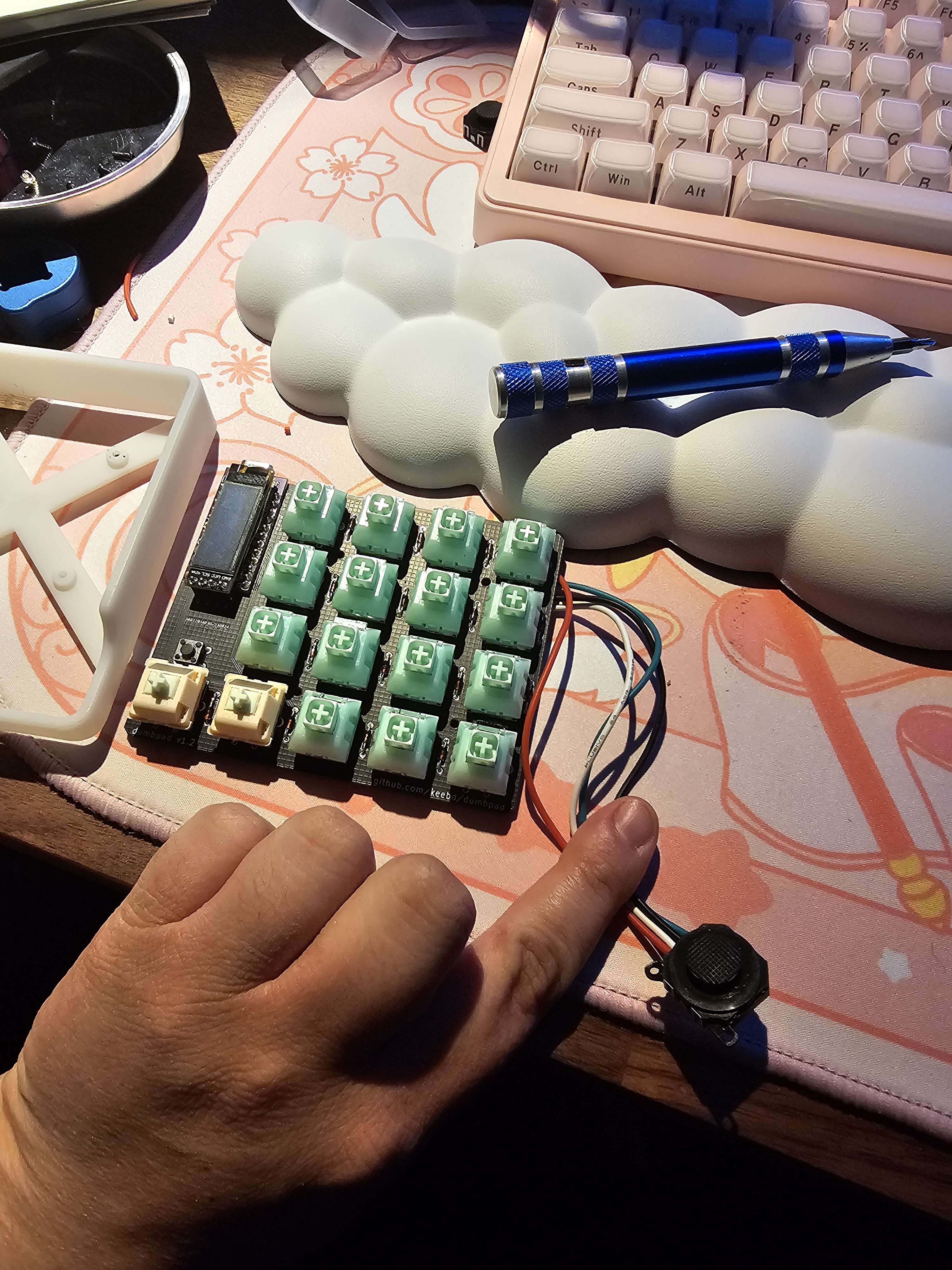
I designed a few iterations- first I taped the joystick on just to get a feel for where my hand fell on the board. This was a pretty ‘eclectic’ process. I just felt around, trring to see where I would enjoy it most. I quickly realized that I would need to have some kind of wrist rest to stabilize it as I moved the joystick.
Iterated througha few designs using some filament colors I didn’t like:
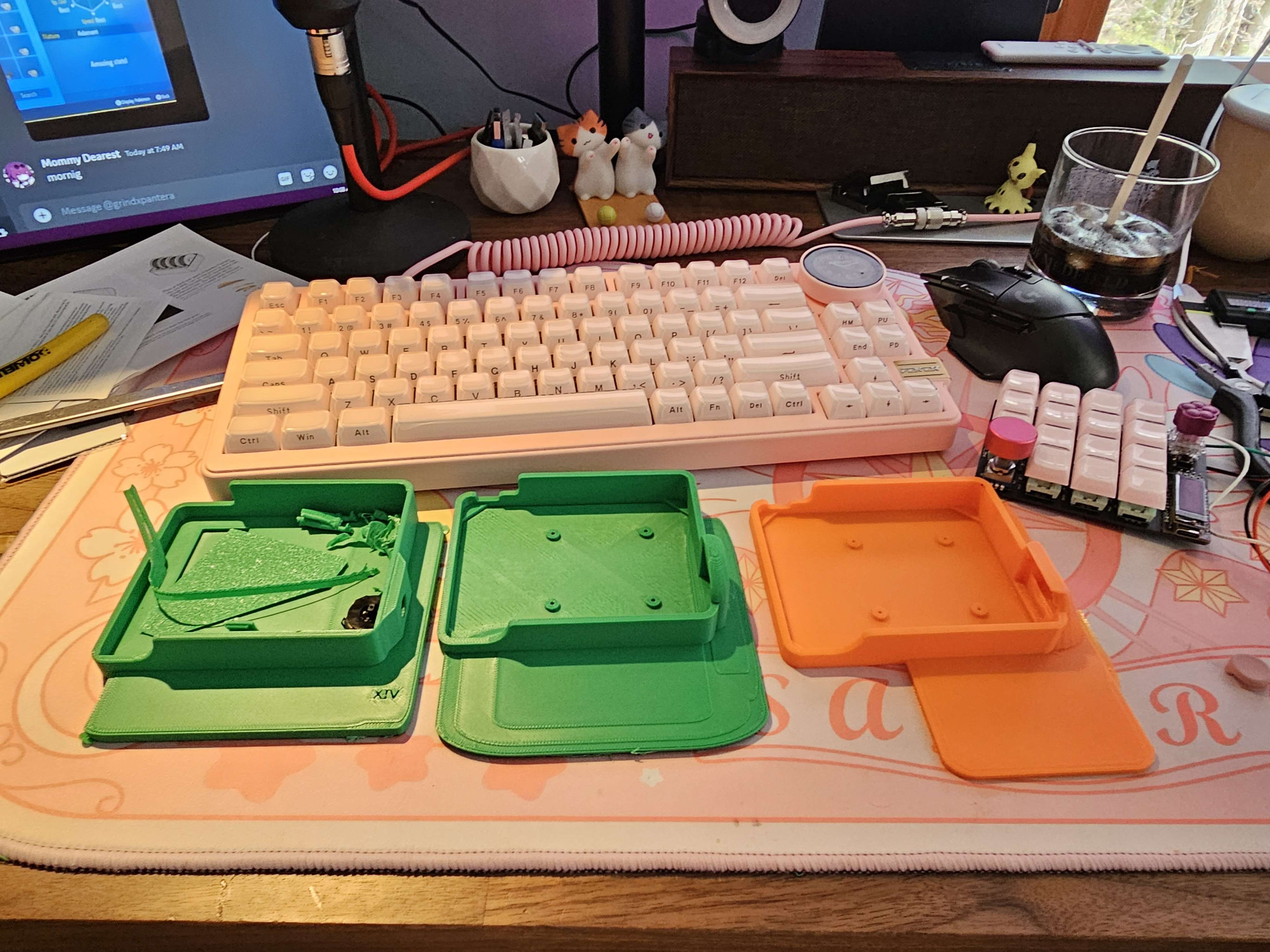
Eventually a lovely friend suggested I separate it into modular pieces so that I could remove the wrist rest and hide the bulky pieces when I wasn’t playing!
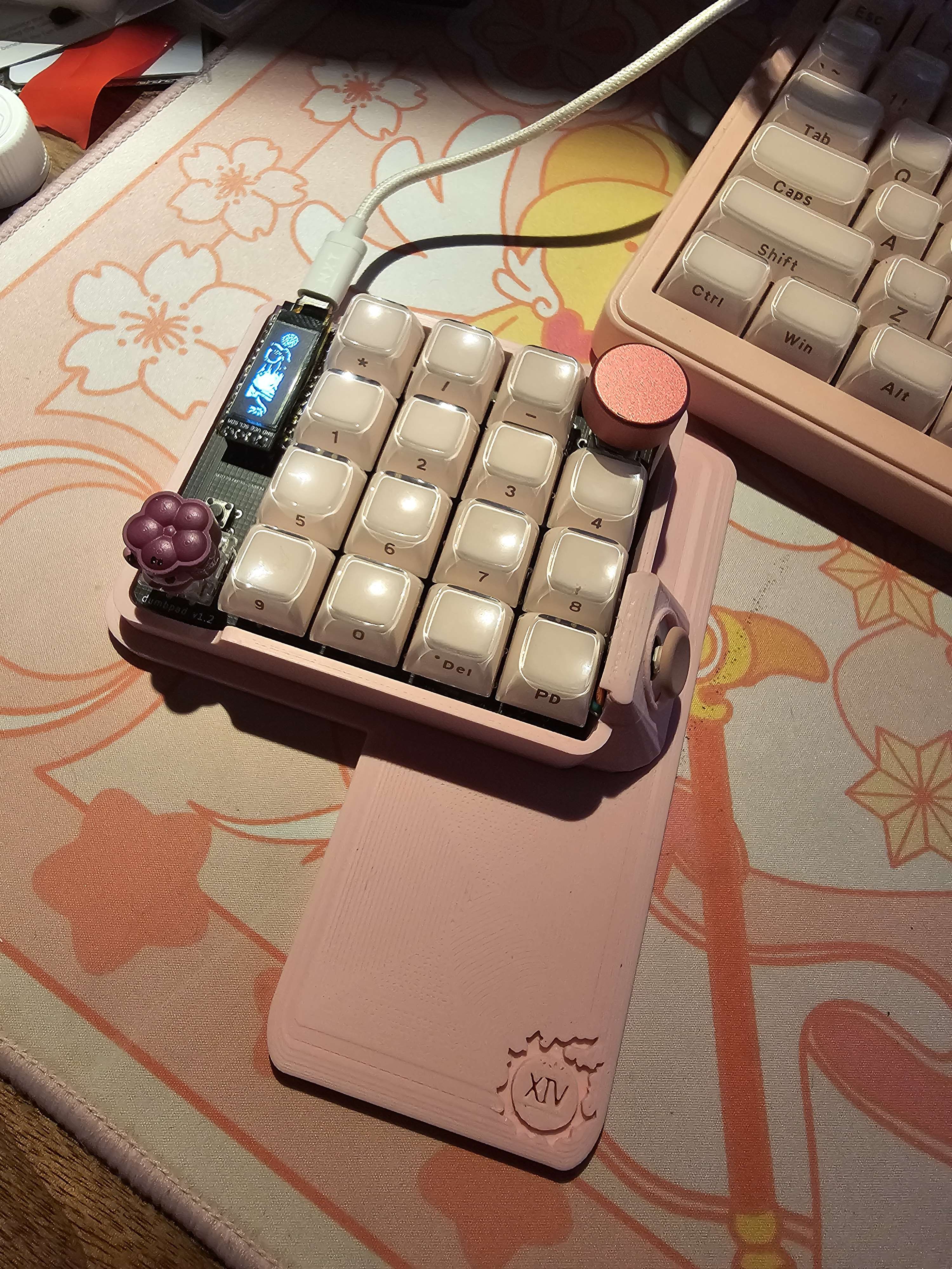
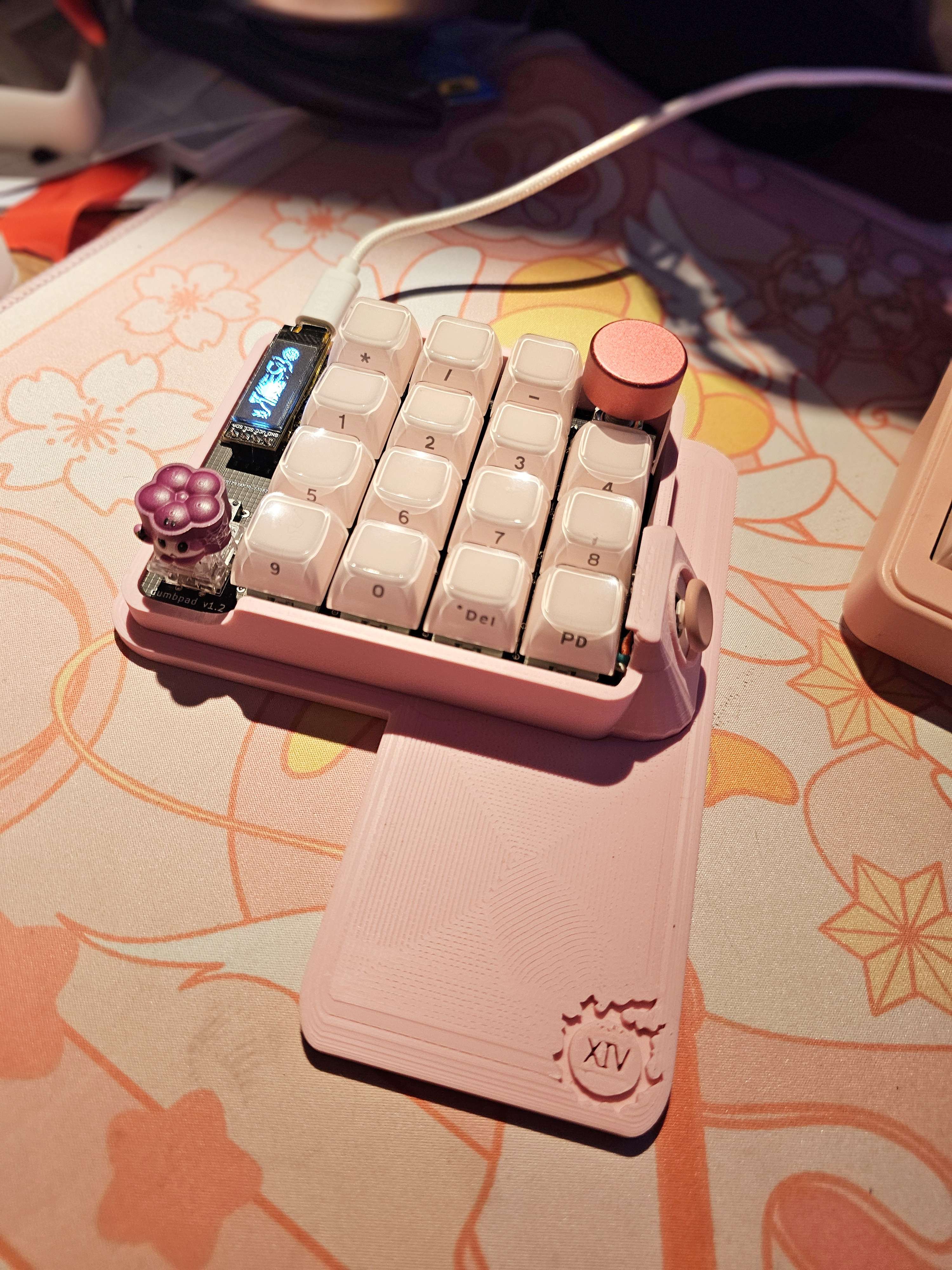
Here are some pics of the completed project:
Anyway- That is all for this project, let me know if you have feedback or questions! You can send any questions you might have here!!